The Flydra Trigger Device
Overview
The Flydra Trigger Device serves to provide a synchronized trigger signal to all cameras providing input to the Main Brain. By use of a custom trigger device, precise timing of frame-by-frame inputs can be verified. (See the source of the flydra_analysis_get_2D_image_latency script for an example.) Furthermore, additional experimental components can be triggered by the device by use of the External Device Trigger.
Fundamentally, the device is a Motmot CamTrig device placed in a custom enclosure with some minimal additional circuitry and custom firmware.
The primary connections are A) the USB interface, which connects to the Main Brain computer, and B) the Camera Sync Triggers, which connects to the flydra cameras.
In addition the External Device Trigger, can be used to trigger experimental devices via a software command from the Main Brain computer over the USB interface.
Internal connection details
The Camera Sync Triggers are the bottom row of BNCs on the device. Internally, they all share the same input. This is a direct connection from the AT90USBKEY J5 pin 4 (and thus Port C6, OCR3A, of the AT90USB1287). Optionally, an op-amp to provide a 5V trigger signal may be added (see below).
External Device Trigger 1 is the top left BNC on the device. Internally, this is a direct connection from the AT90USBKEY J5 pin 9 (and thus Port C1 of the AT90USB1287). Optionally, an op-amp to provide a 5V trigger signal may be added (see below).
External Device Trigger 2: Internally, this is a direct connection from the AT90USBKEY J5 pin 8 (and thus Port C2 of the AT90USB1287). Optionally, an op-amp to provide a 5V trigger signal may be added (see below).
External Device Trigger 3: Internally, this is a direct connection from the AT90USBKEY J5 pin 7 (and thus Port C3 of the AT90USB1287). Optionally, an op-amp to provide a 5V trigger signal may be added (see below).
Optional 5V outputs
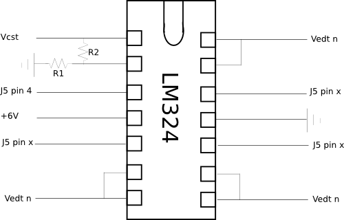
An optional Op-Amp may be used to boost the output signal voltage from 3.3V to 5.0V and provide more current. Furthermore, it should provide a degree of protection to the microcontroller from from adverse connections.

In the drawing above, VCST are the Camera Sync Triggers, VETD n are the External Device Triggers. J5 refers to the jumper on the AT90USBKEY device. The resistors should be chosen to give the appropriate gain. Values of 100 ohms for R1 and 200 ohms for R2 will give a 3x gain, which will saturate the op-amp given a 6V power supply and a 3.3V input from the AT90USB device. The +6 V power is taken from an external power supply, which can be connected into the trigger box via the provided plug.