Wiring the motmot camera trigger
We have been connecting the AT90USBKEY in the following way. We hope to provide details on a canoncial enclosure soon.
Connection details
| Signal | AT90USBKEY contact | AT90USB1287 contact | Op-Amp |
|---|---|---|---|
| Camera Sync Trigger | J5 pin 4 | C6, OCR3A | optional |
| External Device Trigger 1 | J5 pin 9 | C1 | optional |
| External Device Trigger 2 | J5 pin 8 | C2 | optional |
| External Device Trigger 3 | J5 pin 7 | C3 | optional |
| Analog input 0 | J1 pin 10 | F0 | |
| Analog input 1 | J1 pin 9 | F1 | |
| Analog input 2 | J1 pin 8 | F2 | |
| Analog input 3 | J1 pin 7 | F3 | |
| Ground | J5 pin 2, J1 pin 2 |
Optional 5V outputs
An optional Op-Amp may be used to boost the output signal voltage from 3.3V to 5.0V and provide more current. Furthermore, it should provide a degree of protection to the microcontroller from from adverse connections.
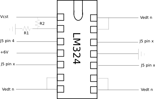
In the drawing above, VCST is the Camera Sync Trigger, VETD n are the External Device Triggers. J5 refers to the jumper on the AT90USBKEY device. The resistors should be chosen to give the appropriate gain. Values of 100 ohms for R1 and 200 ohms for R2 will give a 3x gain, which will saturate the op-amp given a 6V power supply and a 3.3V input from the AT90USB device. The +6 V power is taken from an external power supply, which can be connected into the trigger box via the provided plug.
Example implementation
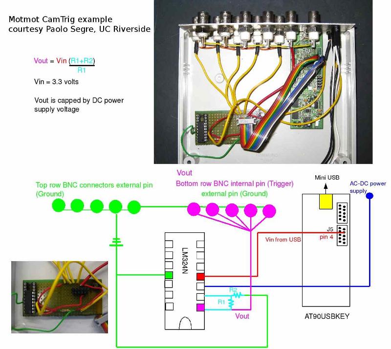
Andrew Straw built the trigger device pictured below, which was photographed and illustrated by Paolo Segre. It is meant to trigger multiple cameras from the Camera Sync Trigger pin, and thus brings this amplified signal out to the bottom row of BNC connectors. (The top row of BNCs is available for exansion and is currently unused.)
![]()
Important links
- Home
- E-mail list archives/signup
- Download
- Screenshot gallery
- paper describing Motmot
- PDF of documentation
Table Of Contents
Previous topic
Motmot camera trigger – firmware build and install instructions